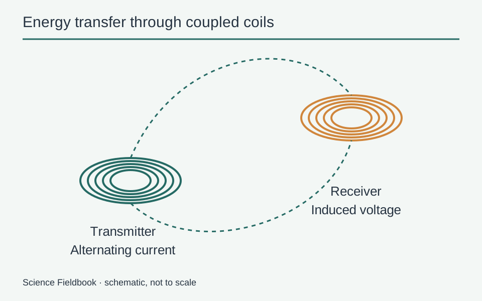
Most phone wireless chargers transfer energy through magnetic induction. Alternating current in a coil inside the charging pad creates a changing magnetic field. A nearby receiver coil in the phone develops a voltage in response to that changing field, and electronics convert and regulate the energy for the battery.
The phone is not pulling a reservoir of loose electricity through the air, and the process is not the same as receiving a radio message from a distant tower. Close spacing, coil geometry, alignment, and control electronics are central to how everyday inductive charging works.
Begin with two electrically separate coils
A transmitter coil is connected to powered electronics in the charging pad. A receiver coil is built into the compatible device. They do not need a direct metal-to-metal electrical contact across the gap between the pad and phone.
Changing current in the transmitter produces a changing magnetic field. Some of that changing magnetic flux links the receiver coil and induces an electromotive force. This is the same broad electromagnetic principle that allows a transformer to transfer energy between circuits.
A steady, unchanging magnetic field is not enough to produce the same continuous induced voltage in a stationary receiver. The time variation matters. That is why the transmitter electronics do more than connect a battery directly to a stationary coil.
The Wireless Power Consortium's explanation of inductive power describes the relationship between the transmitter, receiver, coupling, and efficiency. The educational field lines here are schematic, not a measurement of a particular charger.
How induced voltage becomes battery charging
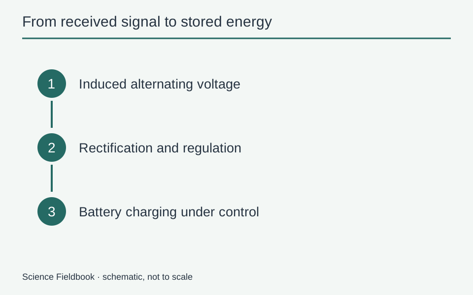
The receiver obtains an alternating electrical signal. A phone battery needs controlled charging under specified conditions, so the received energy passes through rectification and power-management stages rather than entering the cells unchanged.
Rectification changes an alternating signal into a usable DC form. Regulation controls the voltage and current delivered downstream. Battery-management systems monitor relevant conditions and adjust the process rather than treating every incoming watt as automatically safe to store.
The exact architecture varies by product. Some functions may be integrated into one chip or shared with other charging circuitry. A block diagram separates functions to explain the energy path, not to specify the internal layout of every phone.
The distinction between energy transfer and storage is also important in photovoltaic systems. A charger and a solar panel can supply electrical energy, while a battery stores it through electrochemical changes.
Why alignment matters so much
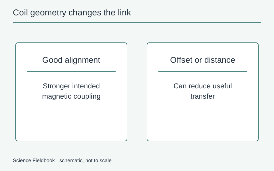
The receiver must link enough of the transmitter's changing magnetic field for useful energy transfer. If the coils are badly offset or too far apart, their coupling becomes weaker. Less useful power may reach the receiver for a given operating condition.
Coil shape, size, orientation, shielding, and the material between them all influence the result. A charger cannot be evaluated by the simple visual rule that any phone placed anywhere on a round pad must receive the same power.
Some systems use magnetic positioning features to help align compatible devices. Those magnets help establish geometry; they are not the main energy source charging the phone. The electrical input to the transmitter still supplies the energy.
Why a thick case can change performance
Adding distance between coils can reduce coupling. Materials in a case or attached accessory may also interact with the field or affect heat flow. The result depends on the actual product design rather than on case thickness alone.
This is why compatibility instructions matter. A material that looks harmless mechanically may still change electromagnetic or thermal behavior. Conversely, many ordinary cases are designed to work with specific charging systems within their intended spacing.
The Consortium's integration guidance notes that housing, coil spacing, shielding, and firmware can affect performance and compliance. That is a system-level issue, not a reason to assume a component alone guarantees a working charger.
Where the lost energy goes
No real charging path is perfectly efficient. Electrical resistance in coils, power conversion, magnetic materials, and other effects can turn some input energy into heat. The phone and pad may therefore become warm during use.
Warmth is not the mechanism that stores charge. It is largely a consequence of losses and the broader charging process. A design seeks to transfer useful power while keeping temperatures within its intended operating conditions.
In a purely illustrative energy budget, if a system receives 10 watts and delivers 7 watts to a chosen output boundary, 3 watts are accounted for elsewhere, including losses. This is arithmetic, not a performance rating for wireless chargers. Measurements must define whether the boundary is the wall socket, transmitter, receiver, or battery.
Why devices communicate during charging
Practical systems need to manage more than a field between coils. They must recognize compatible receivers, negotiate or control power delivery, and respond to changing conditions. Communication and protection functions help make the transfer usable in a consumer product.
Foreign-object detection is one important concern because conductive objects in the wrong place can heat through induced currents. The detailed method depends on the system. An introductory article should not turn that concern into instructions to test arbitrary metal objects on a charger.
Use equipment as its manufacturer specifies, including relevant compatibility and safety guidance. This explanation is not a guide to building, modifying, or bypassing charging hardware, and it makes no claim that every product using a familiar label has identical capabilities.
Inductive charging is not every kind of wireless power
Resonant approaches can use tuned circuits to improve energy transfer under certain coupling conditions. Far-field approaches transfer energy using propagating electromagnetic waves over a different regime. The same broad physics connects them, but their distances, efficiencies, and design constraints differ.
Calling all of them “wireless charging” can hide those distinctions. A phone pad designed for close contact should not be expected to charge the same phone from across a room simply because both arrangements avoid a direct charging connector.
Nor is the effect a controlled static-electricity spark. A spark involves a rapid discharge across an insulating gap; inductive transfer uses a deliberately changing field and a coupled receiving circuit.
Field coupling does not require charge to cross the gap
The transmitter and receiver are separate circuits. Electrons in the pad do not need to leap through the phone's back cover to become the electrons stored in its battery. Energy transfer through the electromagnetic field allows the receiver's own charges to respond within its circuit.
That is a useful distinction from a cable, where the electrical connection provides a direct conductive path between the relevant terminals. Both arrangements ultimately deliver electrical power to charging electronics, but their connection across the boundary is physically different.
The distinction also prevents a misleading visual convention. A bright line drawn between pad and phone can introduce the subject, but it should not be interpreted as a photograph of electricity flowing through open air. The actual near-field pattern is distributed in space and depends on coil currents and materials. An explanatory field drawing should label itself schematic and avoid implying that the depicted lines are visible physical threads.
The takeaway
An everyday wireless charger is a coordinated transmitter, magnetic coupling, receiver, and charging-control system. Alignment and spacing affect the link, while losses and temperature constrain performance. Following those stages explains why “no cable in the phone” still requires careful electrical engineering and why it is not equivalent to unlimited power at a distance.
Related energy-conversion stages appear in electric vehicles, where batteries, power electronics, and motors perform different jobs within one larger system.